
Smart Home Automation Part I - Making Things Do Stuff [LINUX]
Appliance Control
 |
| Smart Home Automation Part I - Making Things Do Stuff [LINUX] |
Making Things Do Stuff
For most people, home automation begins and ends with the principle of appliance control. When any household device such as a video or TV is controlled by something other than a button on its front panel or its original remote control, it is deemed somewhat magical and a topic of further inquiry, particularly if the control is done remotely. Lights and toasters don’t need to be controlled by a wall switch, and your TV doesn’t need to be fed signals from your video, DVD player, or satellite receiver.
Each device has its own idiosyncrasies and control methods, and each has specific functionality that cannot easily be abstracted into any general-purpose form of control interface. However, it is possible to control the vast majority of them using one of two basic methods:
- Mains line-powered control (lightbulbs, toasters, electric teakettles)
- Infrared (IR) remote control (TV, video)
Although modern set-top boxes might have a serial, USB, or network socket on the back, these are in addition to the previous two methods, not exclusive of them. Therefore, being able to control IR signals and the power lines covers the majority of devices in the modern home. Even relatively unsophisticated appliances such as teakettles, which were built without any intention of them being controlled by another means, can be controlled remotely if you know how to control their power source. After all, if you ensure the teakettle is full of water and plugged into a wall-switched socket and the teakettle itself is switched on, then the only necessary task to start the water boiling is to flick the switch on the wall socket—something that can be governed by mains control. And it is these methods of controlling the mains power that I’ll cover first.
X10
X10 is one of the methods I’ll cover that allows you to remotely control the power of any device plugged into the standard ring main in your home. The lights, electric teakettle, and toaster are all examples of existing devices in this category. Additionally, I’ll cover devices that were originally invented to be controlled by X10 such as motorized curtain rails. X10 achieved its market penetration by being fairly cheap and very easy to install.
About X10
X10 is a control protocol that sends data packets along the mains power line with messages such as “turn device on” or “dim to 50 percent.” The data packets are applied to the power lines by a transmitter such as a computer interface or a custom-built remote control, and they’re processed by a much simpler receiver device, such as a light switch, which in turn controls the power to the local device.
X10 works by encoding the data in high-frequency bursts (of 120KHz) and adding it to the existing power line. Because the mains supply in all countries is either 50Hz or 60Hz (with Japan and Tahiti using both!), these high-frequency signals are customarily lost by most devices that are looking only to consume power. On the other hand, a special device can be plugged into the power line that is interested in high-frequency bursts. It is consequently possible to recognize one binary digit of data every time the voltage goes from positive to negative, or vice versa.
CautionSeveral devices are available that are based on this principle, with most do-it-yourself (DIY) stores stocking their own variant. If they do not contain the X10 logo, however, they are not compatible with X10 because their protocols differ. They can also conflict with each other.
Every device that is to be controlled by X10 must have an address. This address comprises two parts:
A house code and a unit code. The house code is simply a letter, from A to P, and should be unique to your house. Obviously, with only 16 letters to choose from, the house code won’t be unique to every house in the world, but it should be unique to any property that shares your immediate mains supply.
This usually comprises your neighbors, and occasionally the property two or three doors down, because all your power lines converge in larger conduits under the road. Consequently, any house that shares these lines will also share X10 messages, making it possible to control your neighbors’ appliances as well as (or instead of) your own. Currently, few enough people are involved in home automation (and specifically X10) for this to be a practical issue. You can provide yourself with some peace of mind right now by placing a filter between the electricity meter and the rest of the house mains. This is usually called a whole house filter, and several makes and models exist, such as the PZZ01, which permits 200A of current. Naturally, with the levels of current involved, many people hire a qualified electrician to install such a device.
The second part of the address is the unit code, of which there are 16, and this is represented by a hexadecimal digit between 0 and F. Although this might not seem a lot, 16 devices allows you to have two appliances (one light and one other) in every room of a moderately sized four-bedroom house.
Most rooms will have only one—the light—while appliances like TVs and radios are more likely to be effectively controlled through infrared or even Ethernet.
In addition to an address, every X10 receiver module fits into one of two broad types, either lamp or appliance. This is a difference that exists in the X10 module itself and that governs how it will deliver power to the device plugged into it and which messages it will accept. An appliance module simply provides on/off control to whatever is plugged into it and usually has a high enough power rating to accept most household appliances (ovens excepted). In contrast, a lamp module will also respond to brightness control messages, varying the voltage applied to the lightbulb plugged into it. Consequently, plugging a toaster into a lamp module can be problematic and a potential fire risk. Adding a light to an appliance module, on the other hand, works fine and only suffers the limitation of losing the dimming
functionality.
NoteSome types of light (such as fluorescent and power-saving bulbs) cannot generally work on lamp modules and must be used with appliance modules.
Each X10 message consists of three parts:
- A start message block (a nibble of 1110)
- An address (a house code and/or unit code)
- A command code (for example, “switch on”)
There are several different commands, fitting mainly into two groups—house code messages directed toward all devices and unit code messages targeting a single appliance. As mentioned earlier, each X10 module is built to accept or ignore specific messages, usually according to whether it’s designated a lamp or appliance module; however, appliance modules will also ignore the “all lights on” message but honor the “all units off,” which is suggested by the subtle wording of the commands differentiating between lights and units. It is interesting to note that their inverse variants (“all lights off” and “all units on”) do not exist. This is intentional. One of the intentions of “all lights on” was to act as a security feature. An accidental invocation of an “all units on” command might start a teakettle dry boiling or something similarly dangerous. Conversely, “all units off” provides a quick closedown procedure for the house.
Once the message has been sent, nothing else happens. Ever! The receiver does not generate an acknowledgment of the message, and the sender doesn’t query the state of the recently controlled device to confirm its arrival. This is because the transmitting circuits are more complex and expensive than the receiver and because adding a message facility would add cost and bulk to the simplest of light switches.
Some two-way switches do exist, providing a way for you to query their state, but they are more expensive.
However, in an attempt to ensure data validity, the message is sent twice, and both messages are compared for equality since electrical noise on the power line could have corrupted part of the signal.
Consequently, it takes around 0.64 seconds for an X10 message to be received. Although this is an accepted facet of the protocol, it is not particularly friendly when guests are staying at your house, since when they try to turn on the light, it appears to have not worked...so they press the switch again and in doing so turn it off! To overcome this, many devices have a local switch that affects the light directly, without sending an X10 message to do so. This is mostly true for X10 light switches that act like a normal in-wall switch but not an in-place X10 socket that is controlled by an existing (that is, normal) light switch.
Another problem that can occur with X10 is that of dead spots, where all messages can (and sometimes do) get swallowed because of the electrical noise generated by certain appliances. The power supplies for some MacBooks are known to have this issue. It is therefore sometimes necessary to move X10 devices to different sockets for them to work. X10 signals are also lost when there is a transformer in the circuit or you have a split phase system. Again, you may need to move both the transmitter and the receiver to the same side of the problem device.
NoteBefore committing to an X10 installation, experiment with a couple of devices to ensure there is a location in the house that is capable of issuing an X10 message that can get heard in the vital majority of other areas.
General Design
Before buying and installing any devices, you must first consider what devices you want to control and how you want to control them. The important part of that question is not how many devices you will use but how they will be controlled. This can be as simple or as complex as you like. And there need not be a computer involved at all.
Simple Case
In this situation, your appliances will be controlled either by their local switches or by one or more wired controllers plugged into the mains. A wired controller is necessary here because you always need some way of introducing the X10 signals to the power line. There are some wired controllers (SD7233), which include timing circuits so they can automatically turn the lights on or off at particular times of day— sometimes within a randomized time frame to confuse potential burglars. These work well and provide a cheaper alternative to running a computer all day, every day.
Other than the basic timer functions, this setup can only be controlled by a human making physical contact with the controllers. It is the cheapest way to begin an exploration into X10, but appliances cannot be controlled remotely via web sites or e-mail or wirelessly from handheld controllers.
If aesthetics are important, there are some controllers (for example, TMD4, shown later in Figure (1-11) that will fit into a wall outlet, allowing you to use the existing light switches to control multiple lights without a Star Trek–like controller on the coffee table. However, this requires the purchase of both an X10 switch (to send the message) and an X10 light fitting (to respond to it) and is usually overkill for such simple setups.
Standard Case
The next step after the simple case shown earlier is to utilize wireless controllers. Most of the equipment on the market uses radio frequency (RF, at 433MHz), allowing devices to be controlled from the garden, through walls, through floors, and through ceilings. The precise range varies according the materials through which the signal is traveling, the other devices operating in the 433MHz range such as TV senders or RFID readers, and the strength of the transmitter, with some mid-price devices having a 25- meter range when unobstructed.
Since RF has no connection to the power lines, it also requires the use of an RF-to-X10 gateway, which plugs into a wall socket, picks up the RF signals sent by any suitable controller, and places the data message onto the X10 power line. Although such devices have a configurable house code, their unit code is invariably hard-coded to one, so be sure to avoid using such a code for any devices if you plan on migrating from a simpler environment.
Adopting an RF-to-X10 gateway in this way provides a lot more scope for automation, because controllers are wireless and no longer need to be situated next to a power socket, enabling them to appear in bathrooms where such sockets contravene domestic housing regulations in many countries by being within 1.5 meter of a water tap, as is the case in the United Kingdom, for example. There are RF controllers that stick to walls, sit on desks, and even fit on key rings!
The primary issue with RF remote control is that rogue transmissions are very difficult to filter out, meaning someone outside could conceivably control your inside lights.
Fully Automated
The big difference between this and the standard automated example is the inclusion of a computer interface, generally the CM11, covered later and shown in Figure 1-14. This doesn’t have an X10 address, but it passively monitors the messages on the power lines and passes them back to the computer via the serial or USB port. Similarly, the computer can use the device to place new messages onto the power lines, which will be picked up by the devices you already have. Once a computer is involved, the possibilities open up. I’ll be covering these possibilities later in this chapter when covering the range of available X10 devices.
It is perfectly possible to have a fully automated solution using the computer that doesn’t use RF wireless or suffer its problems. Instead of RF, you can use a more secure transport and protocol such as HTTPS through a web browser that could be on an iPod touch, iPhone, or other suitably connected handheld device such as a mobile phone to send the message to the computer, which is turn places suitable data on the power line.
Assigning Addresses
Since every automated device in your house needs an address, it makes sense to assign them something sensible and memorable at the start of the process. The most important thing to remember here is that your X10 configuration can grow as your budget increases, and you’re more likely to add a couple of new appliances in your house than you are to add a couple of new rooms!
Determining a house code is simple enough. If you have a neighbor, or neighbors, with an X10 setup, then pick any letter that isn’t used by them. It might sound obvious, but you should talk to them about whether they have one and what codes they’re using. Just because you’re not seeing any irrational behavior at the moment doesn’t mean there won’t be a conflict in the future. I would also avoid using P, since some devices (the TM13UAH, for example) considers P as “accept message on any house code,” which could be confusing and problematic. My only other advice here is to avoid A, which is the default for most equipment. This has two benefits. First, it ensures that anyone “playing” with X10 devices in the neighborhood won’t accidentally stumble onto your network and cause mischief. The second is that by switching away from the defaults, you can be sure that the system was successfully reprogrammed and is not working temporarily by a happy coincidence.
Producing assignments for the unit codes is a matter for your own judgment, but you cannot go far wrong by creating a pattern. I began by numbering my devices at 2 and worked around the rooms in my house in a counterclockwise order, starting upstairs and ending in the kitchen. I assumed two devices per room. My reasoning and thought processes were as follows:
- Start at 2 because 1 is used by the RF-to-X10 gateway.
- Two devices per room means each room starts at 2, 4, 6, 8, and so on, which is easy to remember.
- The only time I need to know the numbers by heart is when fumbling with the remote in the dark. This is when I’m in bed looking for a light switch. Since the master bedroom is upstairs, I start counting upstairs. And when lying in bed, I’m facing the rest of the house, with the second bedroom directly in front of me, and the third to its left, which makes a counterclockwise motion more natural.
- If the split between upstairs and downstairs hadn’t occurred on unit code 8, I would have left a gap so that it did.
- I split the lounge/dining room into two logical rooms, even though it’s one space. This means I can have up to four devices in the one space, which is likely to happen with larger open-plan areas.
- The kitchen is more likely to gain devices over time, so I kept that last in the list.
The final consideration concerns the physical size of the controller modules you plan on using, since many support only eight devices. If your most convenient numbering system happens to use devices 9–16, then you will either have to rethink your pattern or buy only larger controllers.
Using Multiple House Codes
It is possible to have two or more house codes within a single property, bringing the total number of household devices up to a maximum 256. That’s enough for the largest of mansions! The only consideration with such setups is that a control message such as “all lights off” can be applied only to a single house code. For computer-based control, you can easily adapt the software to send two (or more) messages of the “all units off” variety, which affect all devices on the specified house code. However, if you’ve elected to use only stand-alone remote controls, such as the desktop controllers you will learn about later, this can require some fiddling as you switch off each house code in turn. In this case, you would probably want to split up the house codes into the first floor, second floor, and so on, and have a separate controller for each floor.
Device Modules
I’ll now cover the multitude of devices available on the market that can be controlled by X10, in other words, those that contain a receiver. These break down into three categories:
- Internal: Where the X10 receiver and the thing it controls are within the same physical form factor. An example is motorized curtain rails.
- Local control: The X10 receiver processes the message but controls the power to something directly wired into it. An example is light switches.
- Plug-in modules: These fit into a standard power socket, and an external device is plugged into them. The X10 logic determines whether to allow the flow of current between them. An example is appliance units.
Controlling Lights
This is by far the most common type of device, and accordingly there are several different devices to choose from, all known in X10 parlance as lamp modules. However, it should be noted that some lights cannot be attached to lamp modules at all. These include the fluorescent lighting strips found in most kitchens and their compact fluorescent lamp equivalents (often known as energy-saving bulbs) now making their appearances in homes around the country. To make matters worse, these bulbs can also introduce spikes on the power line that can turn off nearby X10 lights. The primary functional difference between the various lamp modules is whether the device in question supports dimming. When a light is dimmed, the alternating voltage is not reduced in amplitude. Instead, small portions of the power sine wave are removed, which effectively turns off the lamp for short periods of time.
Consequently, the bulbs filament is charged and discharged many more times a second than usual, which creates a changing electromagnetic field. This can result in the filament starting to vibrate and creating an audible hum. This is not usually a problem with lightbulbs (and you can always buy rough service bulbs that hold the filament steadier to prevent this movement), but it is dangerous to other appliances that are not built for it. Note that many countries are phasing out the old incandescent lightbulbs.
Lamp Module (LM12U)
This is a simple affair that requires zero installation. You simply plug it into a free wall socket, set the address using the dials on the front, and plug your lamp into the socket on the front, as shown in Figure 1-1.
 |
| Figure 1-1. The LM12U lamp module, 122 ×52 ×42mm |
This will support any incandescent lamp between 60 and 300 watts and can be switched on and off or dimmed by any X10 controller set to the same house code. The LM12U has a sister device, the AM12U, which works in the same work. The primary difference is that the AM12U is intended for appliances and therefore ignores any “dim” messages. The LM12U will also respond to two special messages, “all lights on” and “all units off,” provided they are sent using a matching house code. This module, like many of the others featured here, is placed in series with the power line acting like a logical AND gate. That is, both the lamp’s switch and the power switch at the wall must be on for the X10 “turn on” message to have any effect.
NoteThe code numbers given here are for the U.K. versions of these devices. Because of slightly—but significantly—different power systems used in various countries around the world, alternate modules are required according to your country. The LM12U in Italy, for example, is called the LM12I.
Bayonet Lamp Module (LM15EB)
This is also a simple zero-installation device but one that requires slightly more configuration. To install it, you plug it into an existing light socket and then reinsert the bulb (up to 150W) into its free end. Neither fluorescent lamps nor low-energy lamps should be used, though. The address is set by turning the lamp off and on again and then pressing the required house/unit code on the controller three times, once a second, within 30 seconds of it being switched back on. The light will come on once the code has been learned. There is also a screw-in version of the same device (LM15ES, with ES standing for Edison screw), although it is the bayonet version that’s shown in Figure 1-2.
 |
| Figure 1-2. The LM15EB, 45 ×45 ×95mm |
LM15EBs lack the dimming facility of the larger LM12U, but because they extend only 62mm farther than a traditional fitting, they are small enough to hide inside most lamp shades, making them SWMBOfriendly.
Again, the module acts like an AND gate, allowing the light to shine only when both the X10 command for “on” has been sent and the light switch would normally be on.
Wall Switch (LW10U)
As you can see from Figure 1-3, these are complete replacements for a standard light switch, which means you are limited in styling to white plastic. However, they are easy to fit into existing recessed switch boxes with only 16mm protruding from the wall. The unit’s address is set from a pair of dials placed behind the rocker switch and can be accessed by gently prying it off with a screwdriver. Care should be taken, however, because the plastic lugs that hold the switch onto the case are quite flimsy and would only suffer three or four removals before breaking.
In addition to being controlled remotely by “on,” “off,” “dim,” and “bright” commands, the same functionality is available locally through the switch. Touching it once switches the light to full on or off, whereas keeping it held down will dim the light (if it is bright) or brighten it (if it is dim). Alas, the last brightness is not kept when you switch it off and then on again, nor can you slightly increase the brightness of a dim light without first making it fully dark, but local control means the light comes on immediately after pressing the button so as to not confuse any guests.
 |
| Figure 1-3. The LW10U, 85 ×85 ×30mm |
This device also responds to the “all lights on” and “all units off” messages for matching house codes.
MicroModule with Dimmer (LWM1)
This module is a turbocharged version of the LM10U and is shown in Figure 1-4. It works in the same way as the LM10U but is small enough to fit inside the wall outlet, allowing you to use any switch fascia you prefer.
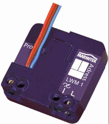 |
| Figure 1-4. The LWM1, 40 ×40 ×15mm |
It supports all the existing functionality of the LM10U but can also remember the last brightness setting, allowing the light to be smoothly changed when it’s first switched on, which helps increases the
bulb life.
NoteThe cheaper modules switch on at full brightness, so if you enjoy mood lighting, then this is a variant worth considering.
Furthermore, this is one of the few devices in this section that supports two-way X10 communication. This means you can send a message to the device asking for its current brightness state, and it is able to reply. This is unavailable with most other devices, meaning you (or more specifically, your controller device) must remember the last message it sent, hoping it arrived, in order to emulate the querying of the lamp’s state. And even this result might be flawed if the brightness was changed locally. In most cases, however, this functionality is unnecessary because you rarely want to know whether the light is on. If you’re going to bed, then you’re not interested is whether the light is on or not, only whether you can switch it off. Unless you have a very large house, you can usually see a single light on in an otherwise pitch-black house and therefore know whether you need to resend the “all units off” message.
The downside of this device is that it costs around three times that of the LM10U. However, there is a midrange product in the LW12 that features the same specification but without two-way communication.
DIN Rail Dimmer (LD11)
This is a (very) high-power module, capable of controlling devices up to 700W, and it is consequently suitable for mains halogen as well as traditional mains lighting. Instead of being used in place of a switch (like the LWM11) or in connection with the bulb (like the LM15EB), this device is remotely placed near the fuse box, with the LD11 output cables running into the light directly. This is a switch terminal on the LD11 that allows the appliance to be switched on and off, as if it were local. However, with four (potentially) long cable runs from the appliance to the LD11 (two for power and two for control, as visible in Figure 1-5), its purpose isn’t so obvious.
 |
| Figure 1-5. The LD11, 50 ×80 ×70mm |
The primarily purpose for the LD11 is mood lighting, thanks to its support for halogens, and scene lighting, thanks to its soft dimming and memory functions. Because they are generally placed away from the devices themselves, you get a much cleaner install. The cost in cabling is thankfully offset by the cheaper cost of the module.
If you use the LD11 to power lighting sockets, they must be used only by lamps, since the dim feature will destroy many other types of appliance. To aid in this, you can use nonconventional plugs and sockets for the lamps and LD11-fed outlets. If your country uses square pin plugs, source some rounded pins, and vice versa.
Appliance MicroModule (AWM2)
This module uses the A prefix because it is primarily intended to control appliances; however, its function is also suited to lights. The AWM2, shown in Figure 1-6, sits inside a standard wall outlet and supports two switches. One switch controls the locally connected lightbulb (and sends an equivalent X10 message onto the power line), while the other switch sends an X10 “on” or “off” messages to the next address in sequence. So, if your AWM2 is configured to E2, you can also control E3 from the same switch.
By installing two identically configured units at the top and bottom of the stairs, you can control both the upstairs and downstairs lights from either location with no rewiring. And since this is an internal module, you can use any switch facing your choose. Note, however, that this device doesn’t support dimming.
 |
| Figure 1-6. The AWM2, 46 ×46 ×18mm |
Controlling Appliances
For appliances that are supplied without X10, such as teakettles, toasters, and HiFi units, a second type of device is needed. These function in much the same way as the LM12U or LM15EB/LM15ES, whereby the device is plugged into an existing power socket and the appliance in question is plugged into the X10 module. As mentioned previously, these require the switch on the wall socket to remain permanently on, along with any switch on the appliance itself. This further implies that any device plugged into such a module that could be controlled remotely must be safe at all times. In the case of the teakettles, for example, it must contain enough water so it won’t boil dry.
Appliance Module (AM12U)
Like its sister module, the LM12U, this is a very simple “plug in and go” device that, although it looks the same (see Figure 1-7), has three very important differences:
- It has no dimmer support.
- It can control fluorescent lights.
- It can operate at much higher loads (up to 500W for incandescent lamps, 1A for
inductive4 appliances like fans, and 16A for resistive loads5 such as heaters). Consequently, its intended purpose is to automate units such as fans and teakettles. However, highpower devices such as vacuum cleaners and fan heaters rarely work on these modules because of the back-EMF created by the collapsing magnetic field around the motor when it is switched on or off. This back-EMF generates a large voltage spike that can blow the fuse in the AM12U (if you’re lucky) or the device (if you’re unlucky).
 |
| Figure 1-7. The AM12U, 52 ×122 ×33mm |
There is an in-wall version of this, called the AW12U, with a similar specification.
NoteYou can often use these devices to automatically power-cycle routers and modems when the Internet connection is unavailable, often from the router being choked or when it simply crashes.
Appliance MicroModule (AWM2)
This is the same module featured previously (and in Figure 1-6) as a suitable candidate for light control, because it can also be used to control appliances. Apart from its smaller size (46 ×46 ×18mm), its main benefit over the AM12U is that it has a much higher power rating, making it possible to power fan heaters and their ilk. The given power specification on this unit is 2kW for incandescent lamps, 3A for inductive appliances, and 16A on resistive loads.
As mentioned previously, this device is mounted in wall outlets, making it more difficult to circumvent. Consequently, this module allows you to switch off a child’s TV or stereo system at night without them simply unplugging it, as they might with an AM12U.
 |
| Table 1-1 gives a breakdown of the previously referenced devices. |
Internal Devices
These devices are rare and usually fit in the novelty category. One good case is REX-10, a barking dog alarm system! Upon receipt of a suitable X10 message (for example, from a motion detector), this device plays the noise of a dog barking followed, a few moments later, by the sending of an X10 message to switch a light on. As an idea it’s good, but it is very difficult to configure these hardwired devices as effectively as you could with a short computer program or simple script.
Combination Devices
I’ll briefly cover some devices that, although they are not supplied with X10 control, are invariably used with it. It should also be noted that the mains control could equally well come from an alternative power control method (for example, C-Bus).
Electronic Curtain Rails: Retrofit
You can automate many curtains by simply wrapping the U-shaped pulling cords around an electric motor. Naturally, the devil is in the details, so there are a few prebuilt motor and pulley systems on the market that are able to open and close curtains, mounted into a head rail. They include the Regency PowerMotion, Universal Curtain Motor (UCM), and the Add-a-Motor 80 (CM80).
Using a retrofit solution requires you to have a good existing head rail, because this determines the maximum weight of the curtain the motor is able to handle—if it gets stuck, then the motor could burn out. The specific weight will vary between devices, but a good guide is that head rails with ball bearings will manage curtains up to 30 kilograms, while those without might stop at 10 kilograms.
All these devices require manual installation to fix the cords to the motor, configure the open and closed positions of the curtains, and adapt the electronics to incorporate a separate X10 receiver.
Depending on the device, this might involve a simple AWM2 or AM12U unit or possibly an in-line
module.
Controlling the curtains once installed is a simple on/off affair, requiring some additional control logic to automatically position them as “50 percent open,” for example; however, you can always issue an “off” command manually to stop them from opening any further. There are switches designed specifically for curtain control, such as the Marmitek X10 Motor Drive Switch (SW10), which repurposes the standard X10 messages of “on,” “off,” and “bright” to be “fully open,” “fully closed,” and “partially open,” respectively.
TipYou should not leave control curtains unattended in the first few days after installation, because the motor might try to move them too far and burn out.
Electronic Curtain Rails: Prebuilt
One such solution here is the Silent Gliss AutoGlide. This provides a made-to-measure curtain track with a premounted motor and a remote-control unit. Since the curtain track is custom made, you must know in advance the size and shape of your window since DIY adaptations are not possible and bending it (to fit in a bay window) is possible only by the manufacturer. The motor can be controlled by an X10 appliance module using a similar amount of DIY to the retrofit versions.
Stand-Alone Controllers
Having lots of remotely controlled lamps and appliances isn’t much use unless you have some way of controlling them. All the devices covered in this section contain an X10 transmitter in some form that places an X10 data message onto the power lines, which is in turn picked up by any of the X10 modules covered previously.
Tabletop Transmitter Modules
These modules all provide a way to send X10 messages from a basic keypad to a specific device. Since they are powered by mains, the signal can be placed directly on the power lines, avoiding the need for an RF-to-X10 gateway. This group supports the largest selection of devices, with each adding its own unique selling points. I’ll cover only a small selection here.
Mini Controller (MC460)
This is a standard, but functional, wired device that supports eight units, switchable in two banks (1–4, 5–8), along with the standard “all lights on”/“all units off” options and brightness control. To reduce the button count, the brightness control only affects the most recent lamp switched, either on or off. This is fairly standard among most transmitter modules.
Sundowner Dusk/Dawn Controller (SD7233/SD533)
On the surface, this appears like the standard mini controller earlier, wired to the mains, with control for eight devices, along with “all lights on”/“all units off” and brightness control. However, it also includes a light sensor that will switch on a predetermined group of lights when it gets dark and turn them off when it’s light again. These brightness settings can be tuned with a little trial and error, although with dusk and dawn changing throughout the year, this can’t necessarily be used as a natural wake-up call.
Mini Timer (MT10U)
This device, shown in Figure 1-8, solves the dusk-’til-dawn problem by using a timer rather than a sensor. This allows you to control up to eight light or appliance modules but lets you preprogram only four of them, making them turn on or off (up to) twice a day. This allows you to mimic a “lived-in” feel for the house. Furthermore, it includes a randomize option, which will vary the programmed times by 30 minutes to give a “human lived-in” feel. This device can also double as an alarm clock.
Both this and the previous device alleviate the need for a computer server, because they can send out predetermined messages according to (simple) logic.
 |
| Figure 1-8. The MT10U, 55 ×150 ×110mm |
Maxi Controller (SC2800)
This device, although designed as part of a security system (MS9780), can also provide full wired control of all X10 devices in the house and is shown in Figure 1-9. Although it doesn’t have any timing functionality, it does have a telephone socket that allows you to dial in from outside and switch lights on or off (by entering the unit code using a Touch-Tone phone, followed by either the * or # key, respectively).
 |
| Figure 1-9. The SC2800 provides easy access to your light switches via telephone. |
 |
| Table 1-2 summarizes these desktop devices |
Handheld Transmitter Modules
These modules work wirelessly and therefore require an RF-to-X10 gateway within range. Otherwise, they perform the same task as the tabletop transmitter modules, except they need batteries to power them.
Handheld RF Remote (HR10U)
These are comparatively cheap devices, capable of controlling all 16 devices in any given house code. They support brightness control but not “all lights on”/“all units off,” and they have arranged the buttons in an on/off order, rather than the more geek-logical off/on.
One useful trait of this device is that it has a strip of card on the left side onto which you can write the names of the appliances that each button controls. Other than that, it’s a fairly straightforward device that “does what it says on the tin.”
There is an even smaller version containing just three device buttons called a Stick-a-Switch (SS13E, shown in Figure 1-10), which is also wireless and can therefore be placed on any wall. This allows you to control devices from the bathroom where mains-powered controllers would be illegal.
 |
| Figure 1-10. The SS13 Stick-a-Switch |
Keyfob Remote (KR22E)
This, almost novelty, device allows you to control four successively numbered devices from your key ring using the “on,” “off,” “bright,” and “dim” messages. It doesn’t have a great range, and the batteries don’t last very long.
EasyTouch Panel10 RF
This Marmitek device is one of the closest to being a cheap touch display. It is a battery-driven RF-to- X10 transmitter (just like the HR10U) but is operated by touching a screen. The screen, however, is merely an image behind a glass panel. That is why it’s cheaper than the other solutions. Although this does prevent you from receiving any visual feedback from the devices, you can customize the image (by making one with GIMP and your printer) and control where on the touch panel the buttons appear; therefore, you can make this appear like a more expensive unit. Unlike the HR10U, which has a fixed set of 16 buttons, this can operate up to 30, providing enough space to control all your lights and other devices through Cosmic, part of the Minerva system (Chapter 7), which lets you set timers, listen to news, and play your MP3 collection using only the basic set of X10 messages.
EasyTouch35 Universal Remote Control
This device’s appearance is that of a traditional “all-in-one” infrared remote control, with separate menus for eight AV devices and the ability to learn the codes from other remotes. However, in addition to its infrared capabilities, it includes an RF transmitter to control X10 devices via an RF-to-X10 gateway such as the TM13.
As a standard IR remote, it works well enough, although the screen when backlit hums slightly. The touchscreen works well, and you can design the menu yourself using predefined icons for each function.
I’ll cover universal remote controls in more detail later in this chapter. For the standard X10 wireless controllers, refer to Table 1-3.

In-Wall Transmitter Modules
These appear like the wall switches I covered earlier insomuch as they hide inside existing wall outlets. However, these do not control any appliance directly. Instead, they solely send an X10 message to a specific device, such as a lamp or appliance module, relying on it to control the hardware attached to it. Therefore, to use these as automatic light switches, you need two devices, the in-wall transmitter and an appliance receiver.
One type of in-wall module is the MicroModule Transmitter Dimmer (TMD4, shown in Figure 1-11), which can command up to four different X10 units from the four switches wired into it. These messages include dimming control if you want to control lights or a simple on/off for appliances.
People with large living rooms and those that enjoy mood lighting and multiple light sources may have four lights in a single room, and this is one of the few devices that lets you control all of them from a simple panel. Note, however, that each light still needs its own lamp module. Of course, it is not necessary for each switch to command an X10 device; it can simply place the message on the power lines and let the PC controller do something with it, such as change the volume on the stereo.
 |
| Figure 1-11. The TMD4 |
Motion Sensors
Most sensors on the market are passive infrared sensors (PIRs) and exist in both indoor and outdoor varieties, with the latter being commonly used as security lights that are mounted in the same area as the sensor. PIRs, like the EagleEye Motion Sensor (MS14), send an “on” message to specific but userselectable X10 modules whenever motion is detected. Most models can also be configured to send “on” and “off” messages at dusk and dawn, respectively. Although some devices can send the message to more than one device (the PR511 and PSH01 spring to mind, both of which contain built-in floodlights), most only communicate to a single device, requiring a computer in your X10 setup to relay this message to other devices if required. You’ll discover how later!
Gateways and Other Exotic Devices
A gateway is any device that allows communication data to flow through it, despite each side of the conversation having different protocols. In most technologies, a gateway performs a two-way function, converting the protocols in either direction. In an X10 gateway, there is generally only one direction, that is, into X10.
The primary device in this category is the TM13U, the RF-to-X10 gateway that I’ve touched upon already. One of these devices, shown in Figure 1-12, allows a wireless RF remote control to place messages onto the power lines for an X10 device to process. It never does the reverse. This device will listen for all RF messages coming from the same house code as is set on its front dial and retransmit them (using the same house code) to the mains line (provided that the socket is switched on). If the dial is set to P, however, it will respond to RF signals for all house codes but retransmit them on the original house code. This device generally has a hardwired address of 1.
 |
| Figure 1-12. The TM13U, 122 ×52 ×33mm, or 224 ×52 ×22mm with aerial extended |
To transmit over two or more phases, you will need a coupler. This will listen for X10 signals on one phase of the mains and replicate it on another. This can either occur in single unit (like the TF678) or require a separate device for each phase that needs to be coupled (an FD10, shown in Figure 1-13).
Both of these coupler devices are, in fact, known as filter/couplers, meaning that instead of duplicating the X10 messages, they can filter them out entirely, thereby preventing the messages from leaking into your neighbors’ houses. And by extension, they can prevent your neighbors’ X10 devices from controlling yours.
 |
| Figure 1-13. The FD10, an interesting filter/coupler module, looking very uninteresting |
A bridge is a device that functions as a go-between for two different protocols. In this context, the protocols invariably exist to bridge home automation systems such as from X10 to C-Bus or from X10 to UPB PulseWorx. Such devices are useful for upgrading systems piecemeal or for controlling very specific devices that don’t exist on your system and/or for which no suitable software drivers exist. However, the cost involved in both the bridging device and the original module would have to be very special to make it worth the money in most cases.
 |
| This, and many other exotic devices, are covered in Table 1-4 |
Computer Control
But far the most powerful and creative device available is a computer interface, such as the CM11, as shown in Figure 1-14. This is a transceiver that’s able to pass messages from the power line to the computer and send messages back from the computer onto the power line. Unlike most X10 devices, the power socket on the CM11 is not controllable by X10 and instead is a simple through port.
Consequently, if you want to control your computer with X10, you have two options.
CautionBe wary about putting the computer’s power onto the normal house code, because you might accidentally switch it off when issuing an “all units off” message.
First, you could assign the computer an unused unit code and configure the computer to issue a shutdown command when it is seen on the power line. (I’ll show you how shortly.) Second, you could use a separate appliance module and simply plug the computer into it. This is a workable although poor solution, since you’re likely to have the machine plugged into an uninterruptible power supply unit (UPS).
 |
| Figure 1-14. The CM11EFL |
In addition to being a controller, this device can also act as an event scheduler and message-relay system, even when not connected to a computer. Therefore, you can use the software (that is, the supplied Microsoft Windows version or a Linux equivalent, such as Heyu) to program the device and let it run stand-alone, since this programmed information now lives within its own EEPROM, which retains the data even if there is no power, allowing it to be moved from one place to another without reprogramming. (This also means it’s possible to have a—slightly—automated house without a single computer!) However, you must keep a copy of the file and data that you uploaded to the CM11, since it is impossible to download it from the device.
CautionWhen unplugging the CM11U from either the mains or the computer, always remove the serial cable from the device first, because stray noise from the cable can affect the internal memory and its settings.
The event scheduler allows you to send any X10 messages at any time of the day, on any days of the week, between any dates of the year. On its own, the device doesn’t have the ability to vary the times randomly, but it does have a dusk and dawn setting that works after you’ve given it details of your physical location as a longitude and latitude. You can find your longitude/latitude from an atlas or (if we’re being serious for a moment) one of the many geo sites on the Web. Your IP address is often accurate enough for these calculations and is available from sites such as the following:
http://api.hostip.info/get_html.php?position=true
http://whatismyipaddress.com
In CM11 parlance, the message-relay system is termed a macro. This allows an X10 message (such as “bedroom light on”) to spawn additional custom messages to any, or all, of your other equipment. A typical macro might consist of “landing light to 50 percent,” “bathroom light on,” and so on. These messages can be separated in time, allowing a single “bathroom light on” message to become a short program such as this:
- Bathroom light on
- Stairs light to 50%
- Wait 5 minutes
- Toilet light off
- Wait 2 minutes
- Stairs light off
So, in short, the CM11 can provide most of the functionality an automated house could want, albeit in a very static way. For your CM11 to dynamically process X10 messages, you’ll need the computer on permanently and some software. Unfortunately, the software with which CM11 currently ships is for Microsoft Windows only. So instead, you can call on the community for software such as Heyu, which
works as a replacement.
Heyu
Heyu is a simple command-line tool, available in most Linux distributions, capable of performing twoway communication with an X10 computer module and of programming the EEPROM with macros and scheduled events. You can also download it from the home page at www.heyu.org. This is not free software or open source as the OSI would consider it, but the source is available for free, and it is free to use.
Once installed, the software autoconfigures itself when first run. This takes a few seconds and involves opening the serial port (/dev/ttyS0 by default) and verifying that the CM11 is truly plugged in and working correctly. The best way of doing this is to include Heyu in the startup sequence by running the following command:
heyu engine
This ensures that the Heyu background process is running, which allows incoming messages to be picked up, triggering external scripts. The engine parameter also starts the state machine inside Heyu, allowing it to remember the last setting for each lamp and appliance, which is useful since many devices (especially the cheaper ones) do not let you query their status. In a noncomputerized environment, this feedback loop is unnecessary since, as a human, you can see whether the light came on when you pressed the button, so you can see if you need to try again. A computer is not as talented.
It is also good design practice for any computer interface to indicate the module’s current state, making this feature more important. If you are likely to be using a lot of computer-based interfaces in your home (say through a web page), then it can be worth upgrading to the two-way lamp and appliance modules covered earlier.
Configuration
The configuration is held within various files inside /etc/heyu, specifically x10.conf, which holds the serial device, default house code, aliases, scenes, and scripts. By default all log information is written to /var/log/heyu.
Aliases, as the name suggests, provide a human-friendly form of the house and unit codes for each device you want to set up in the x10.conf file along with whether the device is a lamp module (StdLM) or an appliance module (StdAM).
ALIAS lounge e5 StdLM
ALIAS stereo e6 StdAM
Once specified, the alias can be used within the configuration file and in the commands issued upon it. This abstraction reduces the number of changes necessary should you ever need to renumber your house appliances.
Scenes are Heyu’s way of describing relay messages or macros. Each line contains a label name and a list of semicolon-separated commands.
SCENE movie_mode on tv; on stereo; dimb lounge 10;
The dim range in Heyu is between 1 and 22 and is supported by relative and absolute brightness change commands (dim and dimb, respectively). Note that if you change the Heyu configuration file while it’s running, you must issue the following command to refresh the parameters:
heyu restart
Sending Messages
This is done simply with commands such as the following:
heyu turn studio on
heyu onstate studio
heyu bright lounge 5
heyu lightsoff _ # the underscore means current house code
which can be placed in larger shell scripts, called out from other languages, or triggered through a web site with CGI. Note that these are all blocking commands, so the rest of the script won’t execute until the X10 messages have been sent—unless you begin the task in background mode, of course.
heyu turn studio on &
These commands can also be placed in your crontab, saving the need to upload changes to the CM11U’s internal EEPROM.
export EDITOR=vi
crontab -e
Then as a sample line, add the following:
30 9 * * 1-5 /usr/bin/play /usr/share/sounds/alsa/Noise.wav
This adds an alarm call at 9:30 a.m. (when else!?) on every day of the month (the first wildcard) in every month of the year (second wildcard) when it’s also a weekday (Monday=1, Friday=5). If you want to add a random element, say within half an hour of 9:30, then you can use some simple bash to instead call this:
00 9 * * 1-5 sleep `echo $((RANDOM%60))m`; /usr/bin/play
/usr/share/sounds/alsa/Noise.wav
Note that I’ve begun the delay 30 minutes earlier but created a random value that lasts up to 60 minutes.
Receiving Messages
Whenever a command is received, Heyu is able to launch an external script as specified in the configuration file. In many cases, this might be to switch on additional lights, acting like a scene or macro:
SCRIPT bedroom on :: /usr/local/bin/heyu turn bedside_light1_mine on
SCRIPT bedroom on :: /usr/local/bin/heyu turn bedside_light2_theirs on
Instead of controlling only lights, it could run an external script. This has the benefit of being editable by a user other than root, it doesn’t require a heyu restart, and it provides a lot of flexibility that can’t be squashed onto a single line. Code such as the following:
SCRIPT bedroom off :: ~steev/bin/housenight
will run a private script that switches off all the important lights and appliances in the house (remember that there is no “all units off” command), post something to your Twitter feed, and play a “Good night” sound effect.
#!/bin/bash
wavplayer default play ~steev/media/good-night-gorgeous.wav
tweet Good night all
/usr/local/bin/heyu turn studio_light off
/usr/local/bin/heyu turn kitchen_light off
/usr/local/bin/heyu turn lounge_light off
shutdown –h now
Alternatively, it can detect a message sent by a sensor transmitter that goes to no device at all but is relayed to several others:
SCRIPT pir_detect_msg on :: /usr/local/bin/heyu lightson _
Instead of controlling X10 devices, you can also control the PC itself. This example intercepts the messages from a single switch to control the volume of the PC to which the CM11 is connected:
SCRIPT E6 on :: /usr/local/minerva/bin/mixer default dec master 10
SCRIPT E6 off :: /usr/local/minerva/bin/mixer default inc master 10
These commands are run with the same user privileges as whoever issued the initial command:
heyu engine
This ensures the commands and devices (such as /dev/dsp) are available to this user. It is possible to build complex scripts and interactions solely using X10 messages. In Chapter 7 I’ll discuss Cosmic.
Programming the EEPROM
All the functionality of the CM11’s EEPROM is available for programming through Heyu. You simply create a text file called /etc/heyu/x10.sched (there is a sample file in this directory also) with a suitable list of commands and type while the CM11U is connected:
heyu upload
The process will convert this text file into a suitable binary image and upload it to the device through the existing serial cable. Since it is impossible to retrieve this data from the CM11, you will want to ensure you keep a backup of the x10.sched file or the resultant image for later use:
/etc/heyu/x10image
The full details of the x10.sched file format are available in the manual, including how to switch date formats to DMY from the default YMD. For now, I’ll include some fragments of my own schedule by way of an example:
macro movies_on 0 dimb lounge 22; 0 on tv; 0 on stereo;
macro lounge_off 0 off lounge; 0 off lounge_table; 0 off tv; 0 off stereo;
timer ...wt.. 01/01-12/31 21:00 00:02 movies_on lounge_off
trigger e1 on movies_on
0 Response to "Smart Home Automation Part I - Making Things Do Stuff [LINUX]"
Post a Comment